# GTU Sem 5 Computer Networks (CN) Summer 2023 paper solutions | 3150710
Q1.)
(a) What is computer network? Describe the various types of network.
Computer Network:
A computer network is a collection of interconnected computers and other devices that can communicate with each other and share resources.
Types of Computer Networks:
- Local Area Network (LAN):
- LANs are networks that typically cover a small geographical area, such as a single building or campus.
- Metropolitan Area Network (MAN):
- MANs have an intermediate scope between LANs and WANs, typically covering a city or a large campus.
- Wide Area Network (WAN):
- WANs cover a larger geographical area, connecting LANs across cities, countries, or continents.
(b) Illustrate various delays which are occurring in data packet transmission.
Processing Delay:
The time required to examine the packet’s header and determine where to direct the packet is part of the processing delay.
The processing delay can also include other factors, such as the time needed to check for bit- level errors in the packet that occurred in transmitting the packet's bits from the upstream node to the router.
It is typically on the order of microseconds or less.
Queuing Delay:
At the queue, the packet experiences a queuing delay as it waits to be transmitted onto the link.
The length of the queuing delay of a specific packet will depend on the number of earlier-arriving packets that are queued and waiting for transmission onto the link.
If the queue is empty and no other packet is currently being transmitted, then our packet’s queuing delay will be zero.
On the other hand, if the traffic is heavy and many other packets are also waiting to be transmitted, the queuing delay will be long.
Queuing delays can be on the order of microseconds to milliseconds in practice.
Transmission Delay:
Packet can be transmitted only after all the packets that have arrived before it have been transmitted.
Denote the length of the packet by L bits, and denote the transmission rate of the link from a router to a router by R bits/sec.
The transmission delay is L/R.
Transmission delays are typically on the order of microseconds to milliseconds in practice.
Propagation Delay:
The time required to propagate from the beginning of the link to router B is the propagation delay.
The bit propagates at the propagation speed of the link.
The propagation speed depends on the physical medium of the link.
Propagations delay=d (Length of Physical Link) /s (Propagation speed in medium).
(c) Explain different network topologies in detail.
A Network Topology is the arrangement with which computer systems or network devices are connected to each other.
Bus
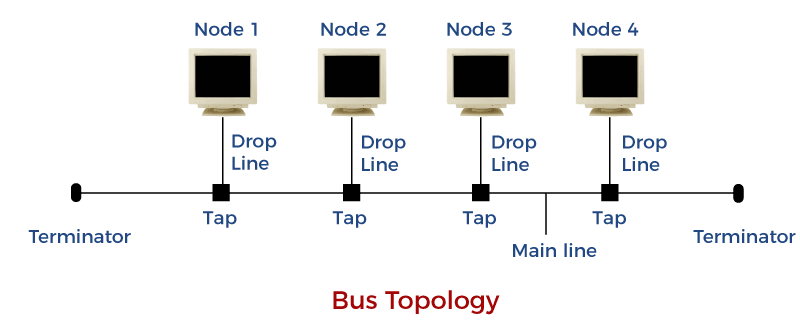
- Bus topology is a network type in which every computer and network device is connected to a single cable.
- It transmits data only in one direction.
- Every device is connected to a single cable.
Star
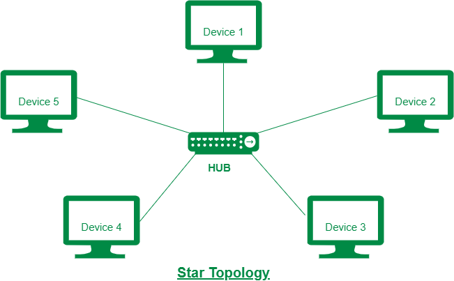
- In this type of topology, all the computers are connected to a single hub through a cable. This hub is the central node and all others nodes are connected to the central node.
- Every node has its own dedicated connection to the hub.
- If the hub is affected then the whole network is stopped because all the nodes depend on the hub.
Mesh
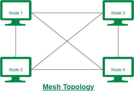
- It is a point-to-point connection to other nodes or devices.
- Each device in the network is connected to every other device in the network.
- Bulk wiring is required in this topology.
Tree Topology
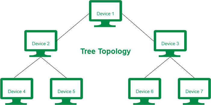
- It has a root node and all other nodes are connected to it forming a hierarchy.
- It is also called hierarchical topology.
- Generally used in Wide Area Network.
Ring topology
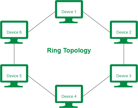
- It is called ring topology because it forms a ring as each computer is connected to another computer, with the last one connected to the first.
- A number of repeaters are used and the transmission is unidirectional.
- Failure of one computer disturbs the whole network.
Hybrid Topology
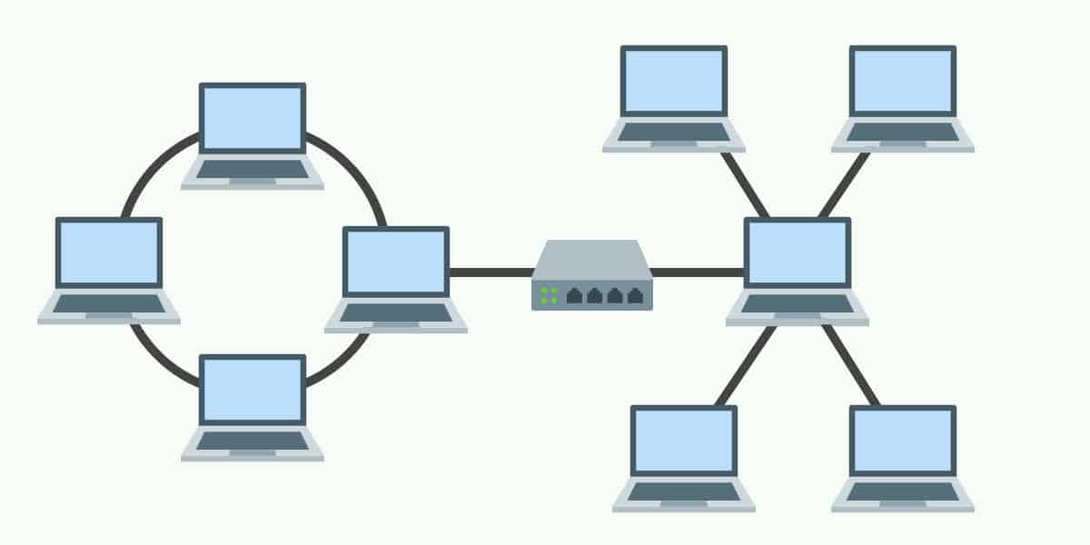
- A network structure whose design contains more than one topology is said to be hybrid topology.
- Combination of two or more topologies.
- It is fairly complex in design.
Q.2
(a) What is web? Explain its architecture.
The web is a global information space on the internet where interconnected documents and resources are accessed through web browsers.
Web Architecture:
- Client: User devices, such as computers or smartphones, equipped with web browsers to access web content.
- Server: Stores and serves web content in response to client requests.
- URL (Uniform Resource Locator): Web addresses that uniquely identify resources on the internet.
- HTTP (Hypertext Transfer Protocol): The protocol governing data transmission on the web.
(b) What is URL? What are its identifiers? Explain them.
URL (Uniform Resource Locator):
A URL is an address used to identify resources on the internet. It serves as a means to specify the location of a resource, such as a web page, document, image, or any other file, and the protocol to be used for accessing it.
Components of a URL:
- Protocol:
- Identifier: The scheme or protocol specifies the method used to access the resource. Common schemes include "http," "https," "ftp," and "mailto."
- Example: In the URL "https://www.example.com," "https" is the scheme.
- Host:
- Identifier: The host identifies the server or domain hosting the resource. It can be a domain name or an IP address.
- Example: In the URL "https://www.example.com," "www.example.com" is the host.
- Path:
- Identifier: The path specifies the location of the resource on the server. It represents the hierarchy of directories or files.
- Example: In the URL "https://www.example.com/page/document.html," "/page/document.html" is the path.
- Query String:
- Identifier: The query string provides additional parameters for the resource, often used in dynamic web pages or web applications.
- Example: In the URL "https://www.example.com/search?q=keyword," "?q=keyword" is the query string.
(c) List and Explain the methods of HTTP.
HTTP (Hypertext Transfer Protocol) defines several methods that indicate the desired action to be performed on a resource. Each HTTP request from a client to a server includes a method, allowing the server to understand how to process the request.
Most common methods of HTTP:
- GET:
- Purpose: Retrieves data from the server. It is a safe method, meaning it should not change the server state and can be repeated with the same result.
- Example: Retrieving (fetching) a webpage, an image, or other static content.
- POST:
- Purpose: Submits data to be processed to a specified resource. It is often used when uploading a file or submitting a form.
- Example: Submitting a form with user input.
- PUT:
- Purpose: Updates a resource or creates a new resource if it does not exist.
- Example: Uploading a new version of a file to a server.
- DELETE:
- Purpose: Requests the removal of a resource.
- Example: Deleting a file on a server.
- PATCH:
- Purpose: Applies partial modifications to a resource. It is used to update a resource with only the changes provided.
- Example: Updating specific fields of a resource without sending the entire resource. Like updating only first name.
- HEAD:
- Purpose: Requests the headers of a resource without the actual data. It is useful for obtaining metadata about a resource without transferring the entire content.
- Example: Checking if a resource has been modified without downloading it.
OR
(c) What is HTTP? Explain Nonpersistent and Persistent connections of HTTP.
Hypertext Transfer Protocol (HTTP) is an application layer protocol. It is used to access data on the world wide web (www). HTTP is a stateless protocol as both the client and server know each other only during the current request.
Nonpersistent Connection:
In a nonpersistent HTTP connection, a new connection is established for each request-response pair. After the response is received, the connection is closed. This approach has some characteristics:
- Connection Overhead: Opening and closing connections for each request can add overhead due to the need to establish and terminate connections repeatedly.
- Latency Impact: The overhead of connection setup and teardown can contribute to increased latency, particularly when making multiple requests.
- Resource Utilization: Resources on both the client and server sides are used for connection management, potentially impacting scalability.
- Example: The default behavior of HTTP/1.0 is to use nonpersistent connections unless otherwise specified.
Persistent Connection:
In a persistent or "keep-alive" HTTP connection, a single connection is maintained for multiple request-response pairs. The connection remains open after a response is received, allowing subsequent requests to reuse the same connection. This approach has several advantages:
- Reduced Overhead: Reusing the same connection for multiple requests reduces the overhead of establishing and closing connections, leading to improved efficiency.
- Lower Latency: With a persistent connection, subsequent requests benefit from the existing connection, resulting in lower latency compared to nonpersistent connections.
- Resource Efficiency: Persistent connections can enhance resource efficiency on both the client and server sides, especially in scenarios involving multiple requests.
- Example: HTTP/1.1 introduced persistent connections as the default behavior, and the "Connection: keep-alive" header is used to signal a persistent connection.
Q.3
(a) Define error detection and correction
- Error Detection:
- Purpose: Identifying the presence of errors in transmitted data.
- Techniques: Common methods include checksums, cyclic redundancy checks (CRC), and parity bits.
- Outcome: If an error is detected, the receiver may request retransmission or take appropriate action based on the error detection mechanism.
- Error Correction:
- Purpose: Automatically correcting errors in transmitted data.
- Techniques: Forward Error Correction (FEC) codes, such as Reed-Solomon codes, are used to add redundancy to the transmitted data, allowing the receiver to reconstruct the original data even if errors are detected.
- Outcome: Correction is performed at the receiver without the need for retransmission.
(b) What is socket? Explain its importance at transport layer protocols.
A socket is an endpoint that establishes communication between two computer processes over a network. It provides a programming interface for network communication, allowing processes on different devices to send and receive data.
Importance at Transport Layer Protocol:
- Endpoint Identification:
- Sockets enable the identification of endpoints for communication. Each socket is associated with a specific IP address and port number, allowing processes on different devices to establish connections and communicate.
- Communication Establishment:
- Sockets play a crucial role in the establishment of communication links between processes. For example, in the Transmission Control Protocol (TCP), a socket is identified by a combination of the source and destination IP addresses and port numbers.
- Data Transmission and Reception:
- Sockets provide an interface for sending and receiving data between processes. This includes methods for transmitting data in a stream (TCP) or datagram (UDP) fashion, depending on the transport layer protocol in use.
- Port Multiplexing:
- Sockets allow for port multiplexing, where multiple processes on the same device can use different port numbers to establish multiple simultaneous connections. This is particularly important for servers handling multiple clients.
(c) Explain User Datagram Protocol (UDP) in detail and discuss how it differs from Transmission Control Protocol (TCP).
User Datagram Protocol (UDP): UDP (User Datagram Protocol) is a connectionless and lightweight transport layer protocol. It provides a minimalistic, best-effort delivery service for transmitting data between applications over a network.
Characteristics of UDP:
- Connectionless:
- UDP operates in a connectionless mode, meaning it doesn't establish a dedicated connection before sending data. Each UDP packet is treated independently.
- Unreliable Delivery:
- UDP does not guarantee the delivery of packets. It lacks mechanisms for error recovery, retransmission, or acknowledgment. If a packet is lost during transmission, UDP does not attempt to recover it.
- No Order Guarantee:
- Packets sent via UDP may arrive out of order. UDP doesn't enforce the ordered delivery of packets, and the application layer must manage and interpret the sequence if necessary.
- No Congestion Control:
- UDP does not implement congestion control mechanisms. It doesn't adapt its rate of transmission based on network conditions, which might lead to network congestion.
- Broadcast and Multicast Support:
- UDP supports both broadcast and multicast communication, allowing a single packet to be sent to multiple recipients simultaneously.
Differences from TCP:
- UDP is connectionless, offering speed without the setup overhead of TCP. TCP is connection-oriented.
- Unlike TCP, UDP provides unreliable delivery without error recovery mechanisms.
- UDP lacks built-in flow control, relying on the application layer for rate management.
- With lower overhead, UDP is used for real-time applications prioritizing rapid data transmission.
OR
Q.3 (a) What is the use of two dimensional parity in error detection?
Use of Two-Dimensional Parity in Error Detection:
- Two-dimensional parity is used in error detection to provide improved reliability in scenarios where data is organized in a matrix or grid structure.
- This technique involves adding parity bits both horizontally and vertically, enabling the detection of errors at both the bit and row/column levels.
- The matrix-based organization facilitates systematic error checking and localization
(b) Explain the wave length division multiplexing in detail
Wavelength Division Multiplexing (WDM):
Wavelength Division Multiplexing (WDM) is used to transmit multiple optical signals simultaneously over a single optical fiber.
- Concept :
- Wavelength Division Multiplexing involves the parallel transmission of multiple signals, each using a distinct wavelength of light.
- Each wavelength corresponds to an independent data channel, allowing for high-capacity communication over a single optical fiber.
- Wavelength Channels:
- WDM systems use different wavelengths of light to represent distinct communication channels.
- Advantage:
- WDM significantly increases the capacity of optical fiber networks by enabling multiple signals to coexist without interference.
- Applications:
- WDM is used in telecommunications, where high data rates and large bandwidths are essential.
(c) Describe flow control and error control in TCP.
Flow Control in TCP:
- Flow control in TCP (Transmission Control Protocol) is a mechanism that regulates the rate at which data is transmitted between the sender and the receiver
- The primary goal of flow control is to ensure efficient and reliable data transfer without causing congestion or data loss.
- TCP achieves flow control through a sliding window mechanism.
- The sender maintains a window size that indicates the maximum number of unacknowledged bytes allowed in the network.
- As the receiver successfully receives and acknowledges data, the window slides, allowing the sender to transmit more data.
- If the window is fully utilized, the sender must wait for acknowledgments before sending additional data, preventing congestion at the receiver.
Error Control in TCP:
Error control in TCP involves mechanisms to ensure the reliable and accurate delivery of data, even in the presence of errors in the network. TCP achieves error control through several techniques:
- Checksums:
- TCP uses a 16-bit checksum to detect errors in the header and data of each segment.
- Acknowledgments:
- TCP uses acknowledgments to confirm the successful receipt of data.
- Sequence Numbers:
- TCP assigns a sequence number to each byte of data transmitted. The receiver uses these sequence numbers to rearrange out-of-order segments and detect missing or duplicated data.
- Retransmission:
- When errors or packet loss are detected, TCP initiates retransmission of the missing or erroneous data. The sender keeps a copy of the transmitted data until it receives acknowledgment from the receiver.
Q.4
(a) What is piggybacking? Explain the advantage of it.
Piggybacking:
- Piggybacking is a the technique of delaying outgoing acknowledgment and attaching it to the next data packet
- When a data frame arrives, the receiver waits and does not send the control frame (acknowledgment) back immediately. The receiver waits until its network layer moves to the next data packet.
Advantages of Piggybacking:
- Optimized Network Utilization:
- Piggybacking reduces the number of separate frames transmitted over the network by combining multiple types of information in a single frame.
- Reduced Latency:
- By combining data frames and acknowledgments, piggybacking can reduce the latency in communication.
- Improved Efficiency:
- Piggybacking enhances the overall efficiency of the communication process.
(b) Write a short note on broadcast and multicast routing.
Broadcast Routing:
- Objective:
- Broadcast routing is designed to deliver data from one source to all possible destinations within a network.
- Method:
- In broadcast routing, the source sends a single copy of the data packet, and network devices, such as routers or switches, replicate and forward the packet to all connected devices.
- Inefficiency:
- While broadcast routing is straightforward, it can lead to network inefficiency, especially in large networks, as every device receives and processes the broadcasted packet, even if the information is not relevant to all devices.
- Example:
- An example of broadcast routing is the Address Resolution Protocol (ARP) in Ethernet networks, where a device broadcasts a message to discover the hardware address of another device on the same network.
Multicast Routing:
- Objective:
- Multicast routing aims to send data from one source to a selected group of destinations rather than to all devices in the network.
- Efficiency:
- Unlike broadcast, multicast is more bandwidth-efficient as it targets only the devices interested in the specific data. Devices need to join a multicast group to receive the information.
- Routing Protocols:
- Multicast routing uses specific protocols, such as PIM, to efficiently route multicast traffic through the network and avoid unnecessary replication of data.
- Example:
- Internet Group Management Protocol (IGMP) is an example of a protocol used for multicast routing. Devices use IGMP to join or leave multicast groups, indicating their interest in receiving or stopping multicast traffic for a specific group.
(c) Explain distance vector routing algorithm.
Distance Vector Routing Algorithm:
- Distance Vector Routing is a type of routing algorithm which is used to determine the best path for routing packets from a source to a destination.
- The algorithm operates based on distance vectors, where each node maintains a table indicating the distance and next-hop information to reach every other node in the network.
Working:
- Distance Vector (DV):
- Each node maintains a distance vector, which is essentially a table containing the distance (cost) to every destination node in the network. Initially, these distances are based on direct neighbors.
- Neighbor Exchange:
- Periodically, nodes exchange their distance vectors with their directly connected neighbors. This exchange allows each node to learn about the distances and paths that its neighbors know about.
- Distance Calculation:
- For each destination, a node calculates the total distance as the sum of the cost to reach its neighbor plus the distance known by that neighbor to the destination.
- Routing Table Update:
- Nodes update their routing tables based on the received distance vectors. If a neighbor provides a shorter path to a destination, the node updates its routing table accordingly.
- Periodic Updates:
- Distance vector updates occur at regular intervals, ensuring that nodes adapt to changes in the network topology. These updates prevent routing loops and help converge to optimal paths.
Advantages:
- Simplicity
- Each node independently maintains its routing information.
- Can adapt to changes in the network topology.
Disadvantages:
- Count-to-Infinity Problem: Can suffer from the count-to-infinity problem, where incorrect distance information takes time to propagate through the network.
OR
Q.4 (a) Discuss the MAC sub layer Design issues?
MAC Sublayer Design Issues:
- Channel Partitioning:
- Issue: How to divide the channel among users.
- Options: Fixed partitioning or dynamic partitioning based on demand.
- Medium Access Control Protocol:
- Issue: Determining rules for channel access.
- Options: CSMA/CD or CSMA/CA protocols for managing access.
- Frame Addressing:
- Issue: Ensuring frames reach the intended destination.
- Options: Physical addressing (MAC addresses) or logical addressing.
(b) Explain datagram networks and virtual circuit networks.
Datagram Networks:
- Concept:
- Datagram networks operate on the principle of sending independent packets, called datagrams, from a source to a destination without establishing a pre-defined communication path.
- Packet Handling:
- Each packet in a datagram network is treated independently and may follow a different route to reach the destination. The network nodes make routing decisions for each packet based on the destination address.
- Example:
- The Internet, specifically the IP (Internet Protocol) layer, is a classic example of a datagram network. IP packets, or datagrams, travel independently, and routers determine the best path for each packet based on the destination IP address.
Virtual Circuit Networks:
- Concept :
- Virtual circuit networks, also known as connection-oriented networks, involve the establishment of a dedicated communication path (virtual circuit) between the source and destination before data transmission.
- Connection Establishment:
- Before data transfer begins, a connection setup phase occurs, where resources along the communication path are reserved, and a virtual circuit is established. This circuit remains in place until the communication session ends.
- Packet Handling:
- Packets within a virtual circuit network follow the established path, ensuring sequential and ordered delivery. Each packet carries a virtual circuit identifier, and routers forward packets based on this identifier.
- Example:
- Frame Relay and ATM (Asynchronous Transfer Mode) are examples of virtual circuit networks. In these networks, a virtual circuit is established, and subsequent data packets follow the predetermined path for the duration of the communication session.
(c) Explain the shortest path routing algorithm.
Shortest Path Routing Algorithm:
The shortest path routing algorithm is designed to find the most efficient path between a source node and a destination node in a network. One of the most widely used algorithms for this purpose is Dijkstra's algorithm:
- Graph Representation:
- The network is represented as a graph, where nodes represent routers or network devices, and edges represent the links or connections between them. Each edge has a weight or cost associated with it, indicating the metric for traversing that link.
- Initialization:
- Assign a tentative distance value to every node. Set the initial distance of the source node to 0 and the distance of all other nodes to infinity. Maintain a set of unvisited nodes.
- Iteration:
- Repeat the following steps until all nodes are visited:
- Select the unvisited node with the smallest tentative distance.
- For the selected node, consider all of its neighbors.
- Calculate the sum of the tentative distance from the source to the selected node and the weight of the edge connecting the selected node to its neighbor.
- If this sum is less than the tentative distance of the neighbor, update the neighbor's tentative distance.
- Repeat the following steps until all nodes are visited:
- Visited Nodes:
- Mark the current node as visited, meaning its tentative distance is final and will not be further updated.
- Termination:
- The algorithm terminates when all nodes are visited, and the tentative distances represent the shortest paths from the source node to all other nodes in the network.
- Path Reconstruction:
- The shortest path from the source to any destination node can be reconstructed by backtracking from the destination node to the source node, following the nodes with the smallest tentative distances.
Q.5
(a) What is the minimum hamming distance?
Minimum Hamming Distance:
- Definition:
- The minimum Hamming distance is the smallest number of differing bits between any two binary strings or code words in a set.
- Significance:
- It is a crucial concept in error detection and correction codes. A larger minimum Hamming distance enhances the error-detecting and correcting capabilities of a code.
- Example:
- For example, in a binary code with words 10101, 11010, 11100, the minimum Hamming distance is 2 (between 10101 and 11100). If any two codewords differ in more than two positions, errors can be detected and corrected.
(b) What is medium access control sub layer?
Medium Access Control Sublayer:
- Definition:
- The Medium Access Control (MAC) sublayer is a component of the data link layer in the OSI model. It is responsible for managing access to the shared communication medium, such as a network channel or a wireless frequency spectrum.
- Functions:
- The MAC sublayer performs functions like channel access, addressing, and framing. It controls how devices in a network gain access to the communication medium, ensuring efficient and fair utilization.
- Channel Access Protocols:
- One of the key roles of the MAC sublayer is to implement channel access protocols, determining how devices contend for and access the shared medium. Examples include CSMA/CD (Carrier Sense Multiple Access with Collision Detection) for wired Ethernet and CSMA/CA (Carrier Sense Multiple Access with Collision Avoidance) for wireless networks.
- Addressing and Framing:
- The MAC sublayer is responsible for adding addressing information to frames, such as MAC addresses, to ensure correct delivery. It also handles the framing of data, delineating the start and end of frames for proper transmission and reception.
(c) Explain in detail ISO/OSI network model with near sketch.
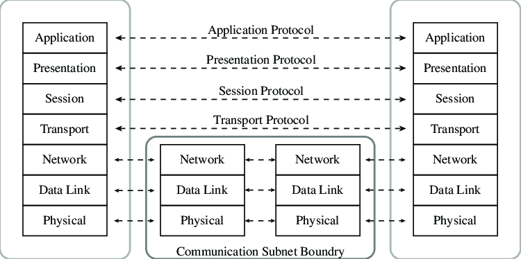
The ISO/OSI (International Organization for Standardization/Open Systems Interconnection) model is a conceptual framework that standardizes the functions of a telecommunication or computing system into seven abstract layers. Each layer represents a specific set of functions and services, and the model provides a systematic way to understand and design network architectures.
1. Physical Layer:
- Functionality:
- Concerned with the physical medium and transmission of raw bits over a physical link.
- Defines characteristics like voltage levels, cable types, and connectors.
- Examples:
- Ethernet cables, optical fibers, electrical signals.
2. Data Link Layer:
- Functionality:
- Responsible for framing, addressing, and error detection within the physical layer's bitstream.
- Manages access to the shared medium and controls flow between devices.
- Examples:
- Ethernet (MAC sublayer), PPP (Point-to-Point Protocol).
3. Network Layer:
- Functionality:
- Handles routing and forwarding of data between devices across different networks.
- Logical addressing, packet forwarding, and routing protocols are implemented at this layer.
- Examples:
- IP (Internet Protocol), ICMP (Internet Control Message Protocol).
4. Transport Layer:
- Functionality:
- Ensures end-to-end communication, reliable data transfer, and error recovery.
- Manages flow control, segmentation, and reassembly of data.
- Examples:
- TCP (Transmission Control Protocol), UDP (User Datagram Protocol).
5. Session Layer:
- Functionality:
- Establishes, manages, and terminates sessions (dialogue) between applications.
- Synchronization, checkpointing, and recovery mechanisms are implemented.
- Examples:
- NetBIOS, RPC (Remote Procedure Call).
6. Presentation Layer:
- Functionality:
- Translates between application and network formats (data encoding, encryption, compression).
- Ensures that data is presented in a readable format.
- Examples:
- JPEG, ASCII, SSL/TLS.
7. Application Layer:
- Functionality:
- Provides network services directly to end-users and applications.
- Implements communication protocols specific to user applications.
- Examples:
- HTTP (Hypertext Transfer Protocol), SMTP (Simple Mail Transfer Protocol), FTP (File Transfer Protocol).
OR
Q.5 (a) What is count-to-infinity problem?
Count-to-Infinity Problem:
- Definition:
- The count-to-infinity problem is a challenge in distance vector routing algorithms where routers may incorrectly converge on suboptimal or looping paths after a network change.
- Example Scenario:
- Consider three routers A, B, and C. After a link failure between A and C, routers B and C might erroneously believe they can reach each other through themselves, leading to a looping path.
- Mitigation Techniques:
- To address the count-to-infinity problem, routing algorithms implement techniques such as split horizon, route poisoning, and hold-down timers. These mechanisms prevent routers from propagating incorrect or outdated routing information and help stabilize the network after topology changes.
(b) State the difference between bit rate and baud rate
Bit Rate:
- Definition:
- The bit rate is the number of bits transmitted per unit of time.
- Measurement Unit:
- It is measured in bits per second (bps).
- Influence:
- The bit rate is influenced by modulation techniques and encoding schemes used in the communication channel.
- Example:
- If each signal element represents one bit (binary 0 or 1), then the bit rate is equal to the baud rate.
Baud Rate:
- Definition:
- The baud rate is the number of signal changes (symbols) per unit of time in a communication channel.
- Measurement Unit:
- It is measured in baud (symbols per second).
- Influence:
- The baud rate is influenced by the signaling method and modulation technique used in the communication channel.
- Example:
- In Morse code, each dot or dash represents a symbol, and the baud rate corresponds to the number of dots or dashes per second.
(c) Describe and discuss the data link layer design issues
Data Link Layer Design Issues:
- Framing:
- Definition: The data link layer frames packets for transmission, delineating the start and end of each packet.
- Design Considerations: Frame synchronization, addressing, and error detection are critical aspects of framing. Various techniques like byte stuffing or bit stuffing are employed to ensure proper synchronization.
- Error Detection and Correction:
- Definition: Detecting and correcting errors introduced during transmission is vital for reliable communication.
- Design Considerations: The choice of error detection and correction mechanisms, such as CRC (Cyclic Redundancy Check) or parity bits, impacts the efficiency of error handling in the data link layer.
- Flow Control:
- Definition: Managing the rate of data transfer between sender and receiver to prevent overflow or congestion.
- Design Considerations: Techniques like windowing and acknowledgments are used for flow control. The design must balance efficient data transfer with avoiding network congestion.
- Link Management:
- Definition: Establishing, maintaining, and terminating links between devices.
- Design Considerations: Link establishment protocols (e.g., PPP's LCP) and link maintenance mechanisms contribute to effective link management. Ensuring timely link termination enhances network efficiency.
- Addressing:
- Definition: Assigning addresses to devices on the network for proper data delivery.
- Design Considerations: Designing addressing schemes and mechanisms for recognizing sender and receiver addresses in the data link layer. MAC (Media Access Control) addresses are commonly used.
- Media Access Control (MAC):
- Definition: Controlling access to the shared communication medium in a multi-access network.
- Design Considerations: MAC protocols, like CSMA/CD (Carrier Sense Multiple Access with Collision Detection) or CSMA/CA (Carrier Sense Multiple Access with Collision Avoidance), play a crucial role. Efficient medium access contributes to reduced collisions and improved network performance.
- Protocols and Services:
- Definition: Defining protocols and services that facilitate reliable communication.
- Design Considerations: Selecting appropriate protocols (e.g., HDLC, PPP) and services (e.g., acknowledging received frames) to ensure data integrity and reliability. The design must align with the specific requirements of the network.