# GTU Sem 5 Computer Networks (CN) Winter 2022 paper solutions | 3150710
Q1
(a) Which of the OSI layers handles each of the following:
i) Dividing the message into segments.
ii) Determining which route through the subnet to use.
iii) Dividing the transmitted bit stream into frames.
i) Dividing the message into segments. : Transport Layer
ii) Determining the route through the subnet to use : Network Layer
iii) Dividing the transmitted bit stream into frames : Data Link Layer
(b) Besides bandwidth and latency, what other parameter(s) is/are needed to give a good characterization of the quality of service offered by network used for (i) Online financial transaction traffic? (ii) Video streaming traffic?
(i) Online Financial Transaction Traffic:
- Reliability: The network should provide a high level of reliability to ensure that financial transactions are completed accurately and securely.
- Security: Robust security measures are essential to protect sensitive financial data from unauthorized access, ensuring the confidentiality and integrity of transactions.
- Jitter: Consistency in latency or jitter is important for financial transactions, as fluctuations in delay can impact the reliability and predictability of the transaction process.
- Packet Loss: Low packet loss is critical to prevent the loss of transactional data and ensure the accuracy of financial information exchange.
- Availability: The network should have high availability to ensure that financial services are accessible whenever needed.
(ii) Video Streaming Traffic:
- Buffering and Playback Smoothness: Consistent and minimal buffering is important for a smooth streaming experience, requiring a balance between bandwidth and buffering capabilities.
- Content Delivery Network (CDN) Performance: The effectiveness of CDN services can significantly impact the delivery speed and quality of video streaming.
- QoS for Real-Time Streaming: Quality of Service (QoS) mechanisms that prioritize real-time streaming traffic over non-time-sensitive data can enhance the viewing experience.
- Adaptability: The network should be able to adapt to varying network conditions, adjusting the streaming quality dynamically based on available bandwidth and other factors.
- Low Latency: While latency is generally associated with interactive applications, low latency is also important for reducing the time it takes for a video stream to start playing after the user initiates playback.
(c) Discuss the circuit switching versus packet switching approaches for moving data through a network of links and switches.
| Circuit Switching | Packet Switching |
|---|---|
| A circuit needs to be established to make sure that data transmission takes place. | Each packet containing the information that needs to be processed goes through the dynamic route. |
| A uniform path is followed throughout the session. | There is no uniform path that is followed end to end through the session. |
| It is ideal for voice communication, while also keeping the delay uniform. | It is used mainly for data transmission as the delay is not uniform. |
| Without a connection, it cannot exist, as the connection needs to be present on a physical layer. | A connection is not necessary, as it can exist without one too. It needs to be present on a network layer. |
| Data to be transmitted is processed at the source itself. | Data is processed and transmitted at the source as well as at each switching station. |
| In-circuit switching has there are 3 phases: i) Connection Establishment. ii) Data Transfer. iii) Connection Released. | In Packet switching directly data transfer takes place. |
| In-circuit switching, each data unit knows the entire path address which is provided by the source. | In Packet switching, each data unit just knows the final destination address intermediate path is decided by the routers. |
| It is not a store and forward technique. | It is a store and forward technique. |
| In-circuit switching each packet follows the same route. | In packet switching packets can follow any route. |
Q2
(a) Justify the statement, “HTTP server is stateless”.
- HTTP (Hypertext Transfer Protocol) is inherently stateless, meaning that each request from a client to a server is independent and devoid of any knowledge about previous requests.
- Unlike stateful protocols, such as those used in sessions or cookies, HTTP doesn't retain information between requests. This statelessness simplifies the architecture, promotes scalability, and enhances reliability by reducing the complexity of server-side management.
- However, it also necessitates the use of additional mechanisms like cookies or session management to maintain continuity and context across multiple requests, enabling applications to recognize users and their preferences over successive interactions within the otherwise stateless framework of HTTP.
(b) State the port number for the following application layer protocols.
i) FTP -21
ii) HTTP-80/8080
iii) SMTP-25
iv) POP3 -110
(c) Discuss the five layer internet protocol stack along with the functionalities of each layer in detail.
While sending a message, the message travels through each layer one by one, starting from the application layer. Each layer adds its own relevant information to the data packet. The packet travels through each layer on the receiving end one by one, starting at the physical layer. Each layer extracts the relevant information, and finally, the message reaches the application layer. We will briefly discuss each layer.
Application layer
- As suggested by its name, the application layer is responsible for communication between applications running on two different end systems. A message or data transferred from one end is readable for the corresponding application on the other end. These applications include web browsers, email clients, etc. At the application layer, the data being transferred is called a message. The protocols used at the application layer include:
- HTTP, FTP, SMTP, DNS.
Transport layer
- On the sending end, the transport layer is responsible for collecting the application layer message from the relevant end-point and transferring it to the network layer to be communicated over the network. The receiving end collects the message from the network layer and passes it on to the relevant end-point where the application layer can access that message. These end-points are called sockets. The transport layer uses a unique identifier called a port number to identify the correct socket or application.
- The message received from the application layer might be broken into chunks at this layer. The transport layers add a header with its own information on top of the message received from the application layer. The unit of data at the transport layer is called a segment.
- The two important protocols used in the transport layer are:
- TCP and UDP
Network layer
- The network layer is responsible for transferring data from one system to another on the network. The transport layer passes a segment and the destination address to the network layer. Then, it is the responsibility of the network layer to transfer the data to the destination end-system over the network. This layer also takes care of the routing of data on intermediate routers.
- The network layer adds a header and a trailer with its information on top of the packet received by the transport layer. The data packet at the network layer is called a datagram. The main protocol used at the network layer to transfer data is Internet Protocol (IP).
- This protocol makes use of IP addresses to identify each system connected to the internet. The two versions of IP protocol are as follows: IPv4, IPv6. ICMP (Error Control)
Link Layer
- When a packet is being transferred over the internet, several intermediate devices are between the two end systems. These devices may be routers, switches, or other computers. The link layer is responsible for communication between one device and its immediate neighbor.
- The protocols and methods used for one link might differ from the protocol used in the next immediate link, even if the destination and data packet remain the same. The link layer adds a header with its information on top of the packet it receives from the network layer. The data packet at the link layer is called a frame.
- The link-layer is mostly implemented in the network adapter/network interface card (NIC), and technologies like ethernet, Wi-Fi, token ring, etc., are associated with the link layer
Physical layer
- The physical layer is responsible for breaking the data frame into bits, converting it into a form that can be transmitted over the physical communication line, and transferring it. This form could be light pulses (fiber-optic), radio waves (for wireless communication, or electric pulses (for wired communication).
- On the receiving end, the physical layer collects the stream of bits and reassembles it into a data frame that is then passed onto the link layer for further processing.
- The protocols and rules used at this layer are dependent on the kind of communication medium being used. For example, ethernet (link layer protocol) has different physical layer protocols for twisted-pair cable, coaxial cable, and fiber optic cable.
OR
(c) Explain User Datagram Protocol (UDP) in detail and discuss how it differs from Transmission Control Protocol (TCP).
User Datagram Protocol (UDP) is a Transport Layer protocol. Unlike TCP, it is an unreliable and connectionless protocol. So, there is no need to establish a connection prior to data transfer. The UDP helps to establish low-latency and loss-tolerating connections establish over the network.
Though Transmission Control Protocol (TCP) is the dominant transport layer protocol used with most of the Internet services; provides assured delivery, reliability, and much more but all these services cost us additional overhead and latency. Here, UDP comes into the picture. For real-time services like computer gaming, voice or video communication, live conferences; we need UDP. Since high performance is needed, UDP permits packets to be dropped instead of processing delayed packets. There is no error checking in UDP, so it also saves bandwidth.
User Datagram Protocol (UDP) is more efficient in terms of both latency and bandwidth.
UDP Header
- UDP header is an 8-bytes fixed and simple header, while for TCP it may vary from 20 bytes to 60 bytes. The first 8 Bytes contains all necessary header information and the remaining part consist of data. UDP port number fields are each 16 bits long, therefore the range for port numbers is defined from 0 to 65535; port number 0 is reserved. Port numbers help to distinguish different user requests or processes.
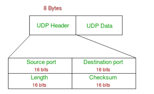 Source Port: Source Port is a 2 Byte long field used to identify the port number of the source.
Destination Port: It is a 2 Byte long field, used to identify the port of the destined packet.
Length: Length is the length of UDP including the header and the data. It is a 16-bits field.
Checksum: Checksum is 2 Bytes long field. It is the 16-bit one’s complement of the one’s complement sum of the UDP header, the pseudo-header of information from the IP header, and the data, padded with zero octets at the end (if necessary) to make a multiple of two octets
Source Port: Source Port is a 2 Byte long field used to identify the port number of the source.
Destination Port: It is a 2 Byte long field, used to identify the port of the destined packet.
Length: Length is the length of UDP including the header and the data. It is a 16-bits field.
Checksum: Checksum is 2 Bytes long field. It is the 16-bit one’s complement of the one’s complement sum of the UDP header, the pseudo-header of information from the IP header, and the data, padded with zero octets at the end (if necessary) to make a multiple of two octets
Applications of UDP
- Realtime Applications
- Streaming Services
- Domain Name System
- DHCP Protocol
- SNMP Protocol
- TFTP Protocol
- IoT Applications
Q3
(a) For the below mentioned internet applications protocol, mention the underlying transport protocol (TCP or UDP). i) Telnet ii) FTP iii) HTTP
TELNET stands for Teletype Network. It is a type of protocol that enables one computer to connect to local computer. FTP stands for File transfer protocol. FTP is a standard internet protocol used for transmitting the files from one host to another. HTTP stands for HyperText Transfer Protocol. It is invented by Tim Berner. HyperText is the type of text which is specially coded with the help of some standard coding language called HyperText Markup Language (HTML). The protocols that are used to transfer hypertext between two computers is known as HyperText Transfer Protocol.
All The Above Given Protocols use TCP.
(b) Discuss the count-to-infinity problem in distance vector routing algorithm with example.
The count-to-infinity problem is a potential issue in distance vector routing algorithms, where routers exchange routing information in order to determine the best path to a destination. The problem arises when there is a change in the network topology, and the routers take some time to converge to the new, accurate routing information. During this convergence period, incorrect or outdated routing information can be propagated through the network, leading to suboptimal routing decisions or routing loops.
ex: In a network with three routers A, B, and C, initially, the distance vector routing tables indicate that the distance from A to C is 4 and from B to C is 2. If the link between A and C fails, Router A updates its distance vector to show infinity for the route to C. However, due to the slow convergence of distance vector algorithms, Router B still receives an outdated advertisement from Router A, indicating a path to C with a metric of 4. Believing this to be a valid route, Router B increments the metric and advertises a path to C with a metric of 5. This misinformation persists, causing a "count-to-infinity" scenario where routers continually increment the metric, resulting in suboptimal and incorrect routing decisions that take time to converge to a stable state.
The solutions to count to infinity problem are : poison reverse, split horizon
The split horizon is a method for resolving instability. Each node in this technique delivers a portion of its table across each interface rather than flooding the table through all of them.
In Poison Reverse, when a router detects that one of its routes has become unreachable, instead of simply updating its routing table with an infinite metric (infinity), it advertises the route back to the source with a special metric that indicates unreachability.
(c) Explain the class-full sub-netting with example.
IP address is an address having information about how to reach a specific host, especially outside the LAN. An IP address is a 32 bit unique address having an address space of 2^32.
Classful Addressing
- The 32 bit IP address is divided into five sub-classes. These are:
Class A, Class B, Class C, Class D, Class E
Each of these classes has a valid range of IP addresses.
Classes D and E are reserved for multicast and experimental purposes respectively. The order of bits in the first octet determine the classes of IP address.
IPv4 address is divided into two parts:
Network ID & Host ID
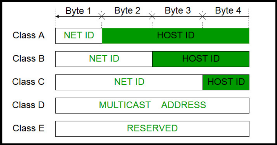
- The class of IP address is used to determine the bits used for network ID and host ID and the number of total networks and hosts possible in that particular class. Each ISP or network administrator assigns IP address to each device that is connected to its network.
Subnetting
Subnetting is the process of creating a subnetwork (also known as a subnet) within a network
Classful subnetting refers to the practice of dividing IP address space based on the traditional address classes (Class A, Class B, and Class C). In classful addressing, the network portion of an IP address is determined by the default class boundaries. Class A addresses have a default subnet mask of 255.0.0.0, Class B addresses have a default subnet mask of 255.255.0.0, and Class C addresses have a default subnet mask of 255.255.255.0.
For example in class C address we can have at most 2^8 (host id) 256 ip addresses and 2^24 (network id) networks. So if the requirement of ip addresses is less than 256 addresses we will be wasting ip addresses, using subnetting we can divide the network in subnetworks by borrowing additional bits from the host id portion. this will allow us to create smaller group of ip addresses.
lets take an example : Class C address, 192.168.0.0, with the default subnet mask 255.255.255.0(/24). Without subnetting, this network has 256 addresses (2^8). Now, suppose we want to subnet this Class C network into four smaller subnets. Borrowing 2 bits allows for 2^2 = 4 subnets. The new subnet mask becomes 255.255.255.192 (/26) because 2 bits are borrowed, leaving 6 bits for host addresses, so now we can address 2^6 hosts means 64 addresses. Note than we cannot use first and last ip address from the range, first ip is network address and last ip is broadcast address. Resulting Subnets:
- Subnet 1: 192.168.0.0/26 (Range: 192.168.0.0 to 192.168.0.63)
- Subnet 2: 192.168.0.64/26 (Range: 192.168.0.64 to 192.168.0.127)
- Subnet 3: 192.168.0.128/26 (Range: 192.168.0.128 to 192.168.0.191)
- Subnet 4: 192.168.0.192/26 (Range: 192.168.0.192 to 192.168.0.255)
OR
Q3
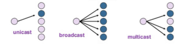
(a) Define the term unicasting, multicasting, and broadcasting.
Unicasting is the process of sending data from one sender to one specific receiver,
Multicasting is sending data from one sender to multiple selected receivers.
Broadcasting is sending data from one sender to all potential receivers in the network.
(b) What is the significance of the following flags in TCP segment? i) URG ii)SYN iii)FIN iv)PSH
Urgent (URG) : Data inside a segment with URG = 1 flag is forwarded to application layer immediately even if there are more data to be given to application layer. It is used to notify the receiver to process the urgent packets before processing all other packets. The receiver will be notified when all known urgent data has been received.
Synchronization (SYN) : It is used in first step of connection establishment phase or 3-way handshake process between the two hosts. Only the first packet from sender as well as receiver should have this flag set. This is used for synchronizing sequence number i.e. to tell the other end which sequence number they should accept.
Finish (FIN) : It is used to request for connection termination i.e. when there is no more data from the sender, it requests for connection termination. This is the last packet sent by sender. It frees the reserved resources and gracefully terminate the connection.
Push (PSH) : Transport layer by default waits for some time for application layer to send enough data equal to maximum segment size so that the number of packets transmitted on network minimizes which is not desirable by some application like interactive applications(chatting). Similarly transport layer at receiver end buffers packets and transmit to application layer if it meets certain criteria. This problem is solved by using PSH. Transport layer sets PSH = 1 and immediately sends the segment to network layer as soon as it receives signal from application layer. Receiver transport layer, on seeing PSH = 1 immediately forwards the data to application layer. In general, it tells the receiver to process these packets as they are received instead of buffering them.
(c) Explain TCP Congestion mechanism in detail.
TCP congestion window and congestion policy are used to avoid network congestion. As the network is the main component in wireless communication, any congestion in a network must be avoided. If the data sent by the sender is not delivered by the network, it must inform the sender about it. The network, other than the receiver also helps in determining the sender's window size.
Congestion is an important factor in packet switched network. It refers to the state of a network where the message traffic becomes so heavy that the network response time slows down leading to the failure of the packet. It leads to packet loss. Due to this, it is necessary to control the congestion in the network, however, it cannot be avoided.
TCP congestion control refers to the mechanism that prevents congestion from happening or removes it after congestion takes place. When congestion takes place in the network, TCP handles it by reducing the size of the sender’s window. The window size of the sender is determined by the following two factors: Receiver window size, Congestion window size
Receiver Window Size : It shows how much data can a receiver receive in bytes without giving any acknowledgment.
Congestion Window size : It is the state of TCP that limits the amount of data to be sent by the sender into the network even before receiving the acknowledgment.
Congestion in TCP is handled by using these three phases:
Slow Start
In the slow start phase, the sender sets congestion window size = maximum segment size (1 MSS) at the initial stage. The sender increases the size of the congestion window by 1 MSS after receiving the ACK (acknowledgment). The size of the congestion window increases exponentially in this phase. The formula for determining the size of the congestion window is Congestion window size = Congestion window size + Maximum segment size
This is how you calculate the size of the congestion window and it goes on for n number of values. The general formula for determining the size of the congestion window is (2)round trip time This phase continues until window size reaches its slow start threshold.
Congestion Avoidance
In this phase, after the threshold is reached, the size of the congestion window is increased by the sender linearly in order to avoid congestion. Each time an acknowledgment is received, the sender increments the size of the congestion window by 1
The formula for determining the size of the congestion window in this phase is Congestion window size = Congestion window size + 1 This phase continues until the size of the window becomes equal to that of the receiver window size.
Congestion Detection
In this phase, the sender identifies the segment loss and gives acknowledgment depending on the type of loss detected.
Case-01: Detection On Time Out
- In this, the timer time-out expires even before receiving acknowledgment for a segment. It suggests a stronger possibility of congestion in a network
- In this, there are chances that a segment has been dropped in the network
- Reaction in response to Detection on time out:
- Setting the threshold to start to half of the current size of window
- Decreasing the size of the congestion window to MSS
- Slow start phase is resumed
Case-02: Detection On Receiving 3 Duplicate Acknowledgements
- This case suggests the weaker possibility of congestion in the network. In this, the sender receives three duplicate acknowledgments for a network segment. The chances are that fewer segments have dropped while the one sent later might have reached.
- Reaction on receiving 3 duplicate acknowledgments:
- Setting the threshold to start to half of the current size of the window
- Decreasing the size of the congestion window to that of the slow start threshold
- The congestion avoidance phase is resumed
Q4
(a) Explain the UDP checksum mechanism for error detection with example.
- Checksum is the error detection method used by upper layer protocols and is considered to be more reliable than LRC, VRC and CRC. This method makes the use of Checksum Generator on Sender side and Checksum Checker on Receiver side.
- At the Sender side, the data is divided into equal subunits of n bit length by the checksum generator. This bit is generally of 16-bit length. These subunits are then added together using one’s complement method. This sum is of n bits. The resultant bit is then complemented. This complemented sum which is called checksum is appended to the end of original data unit and is then transmitted to Receiver.
- The Receiver after receiving data + checksum passes it to checksum checker. Checksum checker divides this data unit into various subunits of equal length and adds all these subunits. These subunits also contain checksum as one of the subunits. The resultant bit is then complemented. If the complemented result is zero, it means the data is error-free. If the result is non-zero it means the data contains an error and Receiver rejects it.
(b) What is the relevance of Type of Service (ToS) and Time to Live (TTL) field in IPV4 packet?
Type of Service (ToS): The ToS field, also known as the Differentiated Services (DSCP) field in modern terms, is a 6-bit field within the IPv4 header. Its primary relevance lies in the realm of Quality of Service (QoS) and prioritization of network traffic. The ToS field allows the classification and marking of packets to specify the level of service they should receive during transmission. Differentiated Services Code Points (DSCPs) are values assigned to packets to indicate their priority or class of service. For example, a network might mark voice or video packets with a higher priority than standard data packets, ensuring timely delivery and improved performance for real-time applications. This prioritization aids in managing network traffic efficiently, enhancing the overall quality and responsiveness of communication.
Time to Live (TTL): The TTL field is a 1-byte (8-bit) field in the IPv4 header that serves a critical role in preventing packets from circulating endlessly in a network. TTL is essentially a counter that is decremented by one each time a router forwards the packet. When the TTL reaches zero, the packet is discarded, and an ICMP Time Exceeded message is sent back to the source. The TTL field prevents packets from indefinitely traversing the network, avoiding potential loops or congested routes. Additionally, TTL serves as a mechanism for determining the maximum hop count a packet can take, contributing to network stability and preventing excessive resource consumption. This field is particularly relevant in large and complex networks where the prevention of routing loops and efficient resource utilization are paramount.
(c) Explain Link State Routing algorithm in detail.
Link State Routing is a dynamic routing algorithm used in computer networks to determine the optimal path for data transmission. Unlike distance vector algorithms, such as RIP (Routing Information Protocol), Link State Routing focuses on maintaining detailed, up-to-date information about the entire network topology. One of the most widely used Link State Routing protocols is the Open Shortest Path First (OSPF) protocol.
Key Components of Link State Routing:
- Topology Database:
- Each router in the network maintains a detailed map, known as the topology database, representing the entire network which includes information about all routers and links, including their states (up or down), link costs, and other relevant metrics.
- Link State Packets (LSPs):
- Routers exchange Link State Packets to share information about their directly connected links and their current state. LSPs contain details such as router ID, sequence number, age of the information, and the list of links with associated metrics.
- Dijkstra's Shortest Path Algorithm:
- Upon receiving LSPs from neighboring routers, each router runs Dijkstra's algorithm to calculate the shortest path to every other router in the network.
Operational Steps of Link State Routing:
- Initialization:
- Routers start with no information about the network. Upon initialization or when a link state change is detected, routers send LSPs to their neighbors.
- Flooding:
- Routers flood their LSPs to all other routers in the network.
- Each router forwards the LSPs it receives to its neighbors, ensuring that all routers eventually have a complete set of LSPs.
- Database Synchronization:
- Routers update their topology databases based on the received LSPs. The databases reflect the current state of the entire network.
- Dijkstra's Algorithm:
- Each router independently runs Dijkstra's algorithm using the information in its topology database to calculate the shortest path to every other router.
- The resulting information is stored in the router's routing table.
- Periodic Updates:
- Routers periodically send updated LSPs to inform neighbors of any changes in their link state.
- This ensures that routers maintain accurate and up-to-date information about the network.
OR
Q4
(a) What are the three most important network-layer functions in a virtual circuit network?
Connection Establishment: In a virtual circuit network, connection establishment involves creating a predefined communication path between source and destination devices. This process includes signaling and negotiation to agree on parameters like bandwidth and quality of service.
- Routing and Forwarding: Routing algorithms determine the optimal path for data transmission within the established virtual circuit. Forwarding involves the actual transmission of packets along the predetermined route using routers and switches.
- Connection Termination: Connection termination in a virtual circuit network ensures a graceful closing of the established path. It involves signaling to inform both ends, releasing resources, and updating routing tables for efficient network resource utilization.
(b) Explain Route Summarization or Route Aggregation in network layer.
Route summarization, also known as route aggregation, is a network design technique used in the network layer to reduce the size of routing tables by consolidating multiple contiguous subnets into a single, more concise route entry. This process aids in improving the scalability and efficiency of routing protocols while minimizing the memory and processing overhead associated with maintaining extensive routing tables.
This technique is commonly associated with classless routing protocols, such as Border Gateway Protocol (BGP) and Open Shortest Path First (OSPF).
Key Aspects of Route Summarization:
Contiguous Subnets: Route summarization is most effective when dealing with contiguous subnets. Subnets that share the same prefix or are adjacent can be aggregated into a single summary route.
Reduced Routing Table Size: By consolidating multiple individual subnets into a summarized route, the size of routing tables is significantly reduced. This is especially important in large-scale networks where the number of routes can become unmanageable without summarization.
Smaller routing tables contribute to more efficient routing table lookup processes, reduced memory usage, and faster convergence times.
Minimized Control Traffic: Summarization helps minimize the amount of control traffic exchanged between routers in the network. This is crucial for bandwidth conservation and optimal network performance.
Increased Scalability: Route summarization enhances the scalability of routing protocols by allowing networks to grow without a proportional increase in routing table size.
(c) Demonstrate the various error detection techniques at data link layer with example.
There are three main techniques for detecting errors in frames: Parity Check, Checksum and Cyclic Redundancy Check (CRC).
Parity Check
The parity check is done by adding an extra bit, called parity bit to the data to make a number of 1s either even in case of even parity or odd in case of odd parity. While creating a frame, the sender counts the number of 1s in it and adds the parity bit in the following way.
- In case of even parity: If a number of 1s is even then parity bit value is 0. If the number of 1s is odd then parity bit value is 1.
- In case of odd parity: If a number of 1s is odd then parity bit value is 0. If a number of 1s is even then parity bit value is 1.
- On receiving a frame, the receiver counts the number of 1s in it. In case of even parity check, if the count of 1s is even, the frame is accepted, otherwise, it is rejected. A similar rule is adopted for odd parity check.
The parity check is suitable for single bit error detection only.
Checksum
In this error detection scheme, the following procedure is applied
- Data is divided into fixed sized frames or segments.
- The sender adds the segments using 1’s complement arithmetic to get the sum. It then complements the sum to get the checksum and sends it along with the data frames.
- The receiver adds the incoming segments along with the checksum using 1’s complement arithmetic to get the sum and then complements it.
- If the result is zero, the received frames are accepted; otherwise, they are discarded.
Cyclic Redundancy Check (CRC)
- Cyclic Redundancy Check (CRC) involves binary division of the data bits being sent by a predetermined divisor agreed upon by the communicating system. The divisor is generated using polynomials.
- Here, the sender performs binary division of the data segment by the divisor. It then appends the remainder called CRC bits to the end of the data segment. This makes the resulting data unit exactly divisible by the divisor.
- The receiver divides the incoming data unit by the divisor. If there is no remainder, the data unit is assumed to be correct and is accepted. Otherwise, it is understood that the data is corrupted and is therefore rejected.
OR
Q5
(a) What is the purpose of Address Resolution Protocol (ARP) and Network Address Translation (NAT)?
- The Address Resolution Protocol is a layer 2 protocol used to map MAC addresses to IP addresses. All hosts on a network are located by their IP address, but NICs do not have IP addresses, they have MAC addresses. ARP is the protocol used to associate the IP address to a MAC address.
- NAT stands for network address translation. It's a way to map multiple local private addresses to a public one before transferring the information. Organizations that want multiple devices to employ a single IP address use NAT, as do most home routers
(b) Explain the following static channel allocations mechanisms:
i)TDMA ii)FDMA
Time Division Multiple Access (TDMA):
- Time Division Multiple Access (TDMA) is a static channel allocation method that divides time into frames and further into time slots. Each user is assigned specific time slots within a frame for data transmission.
- For instance, in a 10-millisecond frame with five time slots, User A may transmit during slots 1 and 2, User B in slots 3 and 4, and User C in slot 5. This sequential time-sharing prevents interference and is commonly used in cellular networks.
Frequency Division Multiple Access (FDMA):
- Frequency Division Multiple Access (FDMA) is a static channel allocation technique that divides the available frequency spectrum into non-overlapping bands. Each user is allocated a unique frequency band for communication.
- In a spectrum from 100 MHz to 200 MHz, for instance, User A may use 100-120 MHz, User B 120-140 MHz, and User C 140-160 MHz FDMA ensures non-overlapping frequency bands, minimizing interference. This method is commonly employed in analog systems such as radio and television broadcasting.
(c) Explain p-persistent CSMA protocol in detail.
- The p-persistent CSMA (Carrier Sense Multiple Access) protocol is a variation of the CSMA protocol used in computer networks to manage access to a shared communication channel. This protocol is commonly employed in Ethernet networks.
- In p-persistent CSMA, "p" stands for the probability of transmission, and the protocol introduces a level of randomness to avoid collisions and efficiently share the channel among multiple users.
Operational Steps of p-persistent CSMA:
Carrier Sensing:
- Before attempting to transmit data, a station using p-persistent CSMA first senses the channel to check for ongoing transmissions.
- If the channel is sensed as idle, the station proceeds to the next step.
Probability of Transmission:
- The station calculates a random number between 0 and 1.
- If the calculated random number is less than or equal to the probability of transmission (p), the station decides to transmit. Otherwise, it defers its transmission and waits for the next slot.
Transmission Attempt:
- If the station decides to transmit, it initiates the transmission of its data onto the channel.
- If the channel remains idle during the entire slot time, the transmission is successful. However, if the channel is sensed as busy during the slot, the station defers its transmission attempt.
Collision Handling:
- Collisions may occur if multiple stations attempt to transmit simultaneously. Collisions are detected through feedback mechanisms like collision detection or collision avoidance.
- In the case of a collision, a backoff mechanism is often employed, and the stations involved in the collision wait for random periods before attempting to retransmit.
Advantages
- Efficient Channel Utilization:
- Randomization:
- Fairness
- Simple Implementation
OR
Q5
(a) Data link protocols almost always put CRC in a trailer rather than in a header. Why?
Data link protocols place the CRC in a trailer rather than a header for efficient processing at the receiver's end. This approach allows the entire frame, including the header and data, to be processed and verified for integrity before checking the CRC, simplifying hardware implementation and accommodating variable-length data fields with consistent error detection.
- The CRC is computed during transmission and appended to the output stream as soon as the last bit goes out onto the wire. If the CRC were in the header, it would be necessary to make a pass over the frame to compute the CRC before transmitting. This would require each byte to be handled twice— once for checksum and once for transmitting. Using the trailer cuts the work in half.
(b) State the difference between bit rate and baud rate.
| Parameters | Baud Rate | Bit Rate |
|---|---|---|
| Basics | The Baud rate refers to the total number of signal units transmitted in one second. | The Bit rate refers to the total Bits transmitted in one unit time. |
| Meaning | Baud rate indicates the total number of times the overall state of a given signal changes/ alters. | Bit rate indicates the total bits that travel per second. |
| Determination of
Bandwidth | The Baud rate can easily determine the overall bandwidth that one might require to send a signal. | The bit rate cannot determine the overall signal bandwidth. |
| Generally Used | It mainly concerns the transmission of data over a given channel. | It mainly focuses on the efficiency of a computer. |
| Equation | Baud Rate = Given Baud Rate / Total Bits transmission in a signal unit | Bit Rate = Total Bits transmission in a unit of signal x Bit rate |
(c) Discuss the working of slotted aloha along with its efficiency in terms of channel utilization.
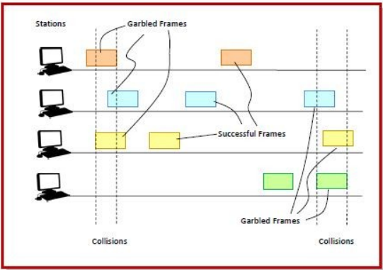
ALOHA is a medium access control (MAC) protocol for transmission of data via a shared network channel. Using this protocol, several data streams originating from multiple nodes are transferred through a multi-point transmission channel. There are two types of ALOHA protocols – Pure ALOHA and Slotted ALOHA.
Slotted ALOHA was introduced in 1972 by Robert as an improvement over pure ALOHA. Here, time is divided into discrete intervals called slots, corresponding to a frame.
Working Principle
- The communicating stations agree upon the slot boundaries. Any station can send only one frame at each slot. Also, the stations cannot transmit at any time whenever a frame is available. They should wait for the beginning of the next slot.
- However, there still can be collisions. If more than one frame transmits at the beginning of a slot, collisions occur. The collision duration is 1 slot. The situation is depicted in the following diagram−
In Slotted Aloha, the efficiency of channel utilization can be calculated using the following formula:
- G is the channel utilization efficiency.
- *G*0 is the offered load, representing the probability of a user having a frame to transmit in a given slot.
Maximum Throughput of Slotted ALOHA
The maximum throughput occurs when G = 1. The maximum throughput is thus : : 36.8%