GTU Sem 5 CN IMP Questions with solutions
Draw the layered architecture of OSI reference model and write services provided by each layer of the model
OSI stands for Open Systems Interconnection. It is a 7-layer architecture with each layer having specific functionality to perform. All these 7 layers work collaboratively to transmit the data from one person to another across the globe.
The OSI model consists of seven abstraction layers arranged in a top-down order:
Physical Layer – Layer 1
The lowest layer of the OSI reference model is the physical layer. It is responsible for the actual physical connection between the devices. The physical layer contains information in the form of bits. It is responsible for transmitting individual bits from one node to the next. When receiving data, this layer will get the signal received and convert it into 0s and 1s and send them to the Data Link layer, which will put the frame back together.
Functions: Bit synchronization, Bit rate control, Physical topologies, Transmission mode
Data Link Layer (DLL) – Layer 2
The data link layer is responsible for the node-to-node delivery of the message. The main function of this layer is to make sure data transfer is error-free from one node to another, over the physical layer. When a packet arrives in a network, it is the responsibility of the DLL to transmit it to the Host using its MAC address.
Functions: Framing, Physical addressing, Error control, Flow Control, Access control
Network Layer – Layer 3
The network layer works for the transmission of data from one host to the other located in different networks. It also takes care of packet routing i.e. selection of the shortest path to transmit the packet, from the number of routes available. The sender & receiver’s IP addresses are placed in the header by the network layer.
Functions: Routing, Logical Addressing
Transport Layer – Layer 4
The transport layer provides services to the application layer and takes services from the network layer. The data in the transport layer is referred to as Segments. It is responsible for the End to End Delivery of the complete message. The transport layer also provides the acknowledgment of the successful data transmission and re-transmits the data if an error is found. At the sender’s side: The transport layer receives the formatted data from the upper layers, performs Segmentation, and also implements Flow & Error control to ensure proper data transmission. It also adds Source and Destination port numbers in its header and forwards the segmented data to the Network Layer.
Functions: Segmentation and Reassembly, Service Point Addressing
Session Layer – Layer 5
This layer is responsible for the establishment of connection, maintenance of sessions, and authentication, and also ensures security.
Functions: Session establishment, maintenance, and termination, Synchronization, Dialog Control
Presentation Layer – Layer 6
The presentation layer is also called the Translation layer. The data from the application layer is extracted here and manipulated as per the required format to transmit over the network.
Functions: Translation, Encryption/ Decryption, Compression
Application Layer – Layer 7
At the very top of the OSI Reference Model stack of layers, we find the Application layer which is implemented by the network applications. These applications produce the data, which has to be transferred over the network. This layer also serves as a window for the application services to access the network and for displaying the received information to the user.
Functions: Mail Services, Directory Services, etc..
What is HTTP? Differentiate its persistent and nonpersistent types with request-response behavior of HTTP
The Hypertext Transfer Protocol (HTTP) is an application-level protocol that uses TCP as an underlying transport and typically runs on port 80. HTTP is a stateless protocol i.e. server maintains no information about past client requests.
HTTP can operate in two modes: persistent and non-persistent, which differ in how they manage the connection between the client and the server.
- Non-Persistent HTTP:
- In non-persistent HTTP, also known as HTTP/1.0, each request from the client requires a separate TCP connection to the server.
- Behavior:
- The client opens a TCP connection to the server.
- The client sends a request, and the server responds with the requested data.
- Once the server sends the data, the connection is closed.
- For a new request, the process repeats, requiring a new TCP connection.
- Drawback: This approach can be inefficient, especially for web pages requiring multiple resources (like images, CSS, JavaScript), as it involves the overhead of setting up a new connection for each request.
- Persistent HTTP:
- Persistent HTTP, introduced in HTTP/1.1, allows multiple requests and responses over a single TCP connection.
- Behavior:
- The client opens a TCP connection to the server.
- Multiple HTTP requests can be sent over this single connection without waiting for each response.
- The server responds with the requested data for each request. The order of responses matches the order of requests.
- The connection remains open for a set period or until the client or server decides to close it. This allows for subsequent requests to be sent over the same connection.
- Advantages:
- Reduces the overhead of opening new connections for each request.
- Faster data retrieval as the connection remains open.
- More efficient use of network resources.
Explain the problem of Count-to-infinity with example in distance vector routing algorithm.
The "Count-to-Infinity" problem is a well-known issue in distance vector routing algorithms. This problem occurs in a network when a link failure causes routers to incorrectly increase their distance vector metrics to infinity due to a slow convergence problem. This can lead to routing loops and suboptimal routing paths.
How it Happens:
Consider a simple network of four routers: A, B, C, and D. Suppose each link has a cost of 1, and routers use the distance vector protocol to determine the shortest path to each other.
Initial State: All routers know the correct distances to each other.
For instance, A knows B is at a distance of 1, C at 2 (through B), and D at 3 (through B and C).
- Link Failure (e.g., Between B and C): When the link between B and C fails, B will update its distance vector, which will increase the distance to C and D (let’s say to infinity, which is a typical practice to represent an unreachable destination).
Propagation of Incorrect Information: B sends its updated distances to its neighbors (A and C). However, C doesn’t know about the direct link failure between B and C.
C thinks it can reach B (at a distance of 1) and updates its routing table. It now thinks it can reach D through B with a distance of 2 (1 to B and 1 from B to D as per B's incorrect information).
Count-to-Infinity: B receives the update from C and now thinks it can reach D through C with a distance of 3 (1 to C and 2 from C to D).
C then updates its routing table, thinking it can reach D through B with a distance of 4, and so on.
This process continues, with the distance metric incrementing each time. This is the count-to-infinity problem, where the routers continuously increase the metric for the unreachable destination.
Explain TCP Congestion control in detail.
TCP (Transmission Control Protocol) congestion control is a mechanism that adjusts the volume of data sent over the network to prevent congestion. Key phases and mechanisms include:
- Slow Start: Begins with a small congestion window (cwnd) and increases exponentially until packet loss is detected or a threshold is reached.
- Congestion Avoidance: After reaching the threshold, cwnd growth becomes linear to cautiously probe for available network capacity.
- Fast Retransmit: On detecting packet loss (evidenced by three duplicate ACKs), the lost packet is immediately retransmitted.
- Fast Recovery: After a fast retransmit, cwnd is reduced and then increases linearly until the network recovers from the packet loss.
- Timeouts: If a timeout occurs, indicating severe congestion, TCP reduces the cwnd significantly and restarts with slow start.
TCP congestion control ensures network stability, fair bandwidth distribution, and adapts to changing network conditions, crucial for maintaining efficiency in data communication.
Explain TCP & UDP in detail and explain how are they different from each other.
TCP (Transmission Control Protocol) and UDP (User Datagram Protocol) are core protocols of the Internet Protocol Suite. They facilitate data transmission between networked devices, but they differ significantly in terms of how they handle this data transfer.
TCP (Transmission Control Protocol)
- Connection-Oriented: TCP establishes a connection before transmitting data using a process known as the three-way handshake.
- Reliability: TCP ensures reliable delivery of data. It retransmits lost packets and acknowledges received ones.
- Ordered Delivery: TCP maintains the order in which packets are sent, ensuring that data is reconstructed in the correct sequence at the receiver's end.
- Flow Control: TCP uses window-based flow control mechanisms to prevent overwhelming the receiver.
- Congestion Control: TCP dynamically adjusts data transfer rate based on network congestion.
- Usage: Ideal for applications where reliability and data integrity are crucial, such as web browsing (HTTP/HTTPS), email (SMTP, POP3, IMAP), file transfers (FTP), etc.
UDP (User Datagram Protocol)
- Connectionless: UDP does not establish a connection before sending data. It sends packets called datagrams with minimal initial negotiation.
- No Guarantee of Delivery: UDP does not guarantee packet delivery. Lost packets are not retransmitted.
- Unordered Delivery: UDP does not ensure the order of packets. The receiving application must handle any reordering.
- No Congestion Control: UDP does not adjust for network congestion, which could lead to packet loss or delay.
- Efficiency: UDP is more efficient and incurs less overhead than TCP because of its simplicity.
- Usage: Suitable for applications where speed is more critical than reliability, like streaming media (video conferencing, live streaming), online gaming, DNS lookups, etc.
| Feature | TCP | UDP |
|---|---|---|
| Connection | Connection-oriented (requires a connection before data transfer) | Connectionless (no prior setup needed) |
| Reliability | Reliable (ensures packet delivery) | Unreliable (no guarantee of packet delivery) |
| Ordering | Maintains order of data packets | Does not guarantee order of packets |
| Speed and Overhead | Slower, due to more overhead | Faster, minimal overhead |
| Use Cases | Ideal for applications needing data integrity and reliability (e.g., web, email) | Suited for time-sensitive applications where speed is crucial (e.g., streaming, gaming) |
| Flow Control | Incorporates flow control to prevent overwhelming the receiver | No flow control |
| Congestion Control | Has built-in mechanisms to adjust for network congestion | Lacks congestion control |
Explain parity check for error detection in data transfer
Parity checking is a simple, widely used method for error detection in data transmission. It involves adding an extra bit to a string of binary data to make the number of set bits (bits with a value of 1) either odd or even. This extra bit is known as the parity bit.
There are two types of parity checks: even parity and odd parity.
Even Parity
In even parity, the number of set bits (including the parity bit) is made even.
If the number of set bits in the original data is already even, the parity bit is set to 0.
If the number of set bits in the original data is odd, the parity bit is set to 1 to make the total count of set bits even.
Odd Parity
In odd parity, the number of set bits (including the parity bit) is made odd.
If the number of set bits in the original data is already odd, the parity bit is set to 0.
If the number of set bits in the original data is even, the parity bit is set to 1 to make the total count of set bits odd.
How it works ?
The sender calculates the parity bit (either even or odd) based on the data bits. The data, along with the calculated parity bit, is then transmitted to the receiver.
The receiver calculates the parity of the received bits (including the received parity bit).
For even parity, if the total number of set bits is even, the data is considered error-free. If it’s odd, an error is detected.
For odd parity, if the total number of set bits is odd, the data is considered error-free. If it’s even, an error is detected.
Describe flow control and error control in TCP
Flow control and error control are two crucial mechanisms in TCP (Transmission Control Protocol) that ensure reliable, stable, and efficient data transmission between networked devices.
Flow Control in TCP
Flow control in TCP is a mechanism that prevents the sender from overwhelming the receiver with too much data at once. It ensures that the sender only transmits as much data as the receiver can handle at a given time.
- Receive Window (rwnd): TCP uses a receive window, which is a buffer space advertised by the receiver. This window size informs the sender how much data it can send before needing an acknowledgment.
- Sliding Window Protocol: TCP implements a sliding window protocol for flow control. As the receiver processes data and frees up buffer space, it updates the window size in the acknowledgment messages, allowing the sender to adjust its transmission rate accordingly.
- Dynamic Window Sizing: The size of the receive window can dynamically change during the session, depending on the receiver's buffer availability and processing speed. This adaptive behavior is crucial for efficient data transfer and network utilization.
Error Control in TCP
Error control in TCP ensures that data is transmitted accurately across the network. It encompasses mechanisms for error detection and correction.
- Acknowledgments (ACKs): TCP uses ACKs to confirm the successful receipt of data. When the sender transmits data, it starts a timer. If the acknowledgment for the data isn't received before the timer expires, TCP assumes that the data was lost or corrupted during transmission.
- Retransmission: In case of packet loss or error, indicated either by the expiration of the timer or the receipt of duplicate ACKs, TCP performs retransmission of the lost or corrupted data.
- Checksum: Each TCP segment includes a checksum field. This checksum helps the receiver detect errors in the header and data part of the TCP segment. If a segment is received with a checksum error, it is discarded, and the sender eventually retransmits it after the timeout.
- Fast Retransmit: Upon receiving a certain number of duplicate ACKs (typically three), TCP assumes that a segment was lost and retransmits it immediately without waiting for the timeout.
- Selective Acknowledgment (SACK): This is an optional feature in TCP where the receiver can inform the sender about all segments that have been received successfully, allowing the sender to retransmit only the missing segments.
Explain the working of CSMA/CD protocol in detail
CSMA/CD (Carrier Sense Multiple Access with Collision Detection) is a network protocol used in early Ethernet technology for local area networking. It is designed to minimize the chances of packet collisions on a shared transmission medium, like coaxial cable. CSMA/CD is essential for understanding how early Ethernet networks managed data traffic and handled collisions.
Working of CSMA/CD Protocol:
Carrier Sense (CS):
- A device wishing to transmit data first checks the network to determine if it is idle (no one else is transmitting).
- If the medium is idle, it begins transmitting. If it’s not, the device waits for the current transmission on the network to end before proceeding.
Multiple Access (MA):
- Multiple devices are connected to the same medium and follow the same procedure to transmit data. This means any device can attempt to transmit data if the medium is free.
Collision Detection (CD):
- While transmitting, the device monitors the medium to see if the data it is transmitting collides with data transmitted by another device.
- A collision occurs when two or more devices begin transmitting simultaneously. The electrical signals on the cable combine and alter the data, making it unreadable.
Dealing with Collisions:
- If a collision is detected, the device immediately stops transmitting and sends a jam signal to inform other devices of the collision.
- After this, the device waits for a random period (using the "backoff algorithm") before attempting to retransmit. This random wait helps reduce the chances of another collision when multiple devices retransmit.
Backoff Algorithm:
- This is a method used by devices to randomize their retransmission attempts.
- After a collision, each device waits for a random period before trying to retransmit, reducing the likelihood of repeated collisions.
Reattempting Transmission:
- If the device detects the medium as idle after the backoff period, it attempts to transmit again. If another collision occurs, the backoff algorithm is run again, and the process repeats.
Maximum Attempts:
- There’s a limit on the number of retransmission attempts (usually 15). If this limit is reached, the device gives up trying to transmit the packet and reports an error.
Applications and Limitations:
CSMA/CD was primarily used in early Ethernet networks (10BASE5 and 10BASE2).
Modern Ethernet networks (Fast Ethernet, Gigabit Ethernet) use switched environments, making CSMA/CD obsolete since the switch eliminates collisions by providing a dedicated segment for each node.
Explain p-persistent CSMA protocol in detail and how is it different from 1-persisent in CSMA/CD?
p-Persistent CSMA is a protocol used in wireless and certain wired network scenarios, particularly where time is divided into discrete slots. It's designed for networks that support time-slotted transmission and can detect the idle state of the channel before the slot begins.
how it works ?
- Checking the Channel: A device with data to send first checks if the channel is idle.
- Slot Time: If the channel is idle, the device waits for the beginning of the next time slot.
- Transmission Decision: At the start of the slot, the device transmits with a probability of 'p' or defers with a probability of '1-p'. If it defers, it behaves as if the slot were busy and waits for the next slot to make another transmit or defer decision.
- Collision and Retransmission: If a collision occurs (when more than one device decides to transmit), each device runs a random backoff algorithm before attempting to transmit again.
The key parameter 'p' can be adjusted to optimize network performance. A higher 'p' means a higher chance of transmission when the channel is found idle, which can lead to more collisions in heavy traffic. A lower 'p' reduces collision risk but can lead to underutilization of the channel.
Differences between p-Persistent and 1-Persistent CSMA
Transmission Probability: In p-persistent, transmission occurs with a probability 'p' in an idle slot, while in 1-persistent, transmission is immediate when the channel is idle.
Network Efficiency: p-Persistent can be more efficient in high-traffic situations by reducing collisions, but it might underutilize the channel in low-traffic situations. 1-Persistent is simpler but can lead to more collisions in high traffic.
Applicability: p-Persistent is often used in slotted networks and is suitable for both wired and wireless networks, while 1-persistent is typically used in CSMA/CD environments like Ethernet.
Explain the working of slotted aloha
Slotted ALOHA is a method of managing communication in a network, specifically designed for shared medium networks where multiple devices attempt to send data over a single communication channel. It's a variation of the original ALOHA protocol and was introduced to improve the efficiency of the network by reducing the likelihood of collisions when packets are transmitted.
Working of Slotted ALOHA:
Time Division into Slots: In Slotted ALOHA, time is divided into equal-sized slots that correspond to the length of a packet. All devices in the network must synchronize their transmissions to these time slots.
Transmission Rules: When a device has data to send, it waits until the beginning of the next slot to transmit its packet. If two or more devices transmit during the same slot, a collision occurs, and none of the packets are successfully transmitted.
Collision Handling: If a collision occurs, each device waits for a random number of time slots before trying to retransmit. This randomization helps prevent the devices from colliding again on their next attempt. The waiting period is typically determined using a random exponential backoff algorithm.
Successful Transmission: If no other device transmits in the same slot, the packet is successfully transmitted without collision. After a successful transmission, the device can send another packet in the next slot or wait if it has no data to send.
Feedback: In most implementations of Slotted ALOHA, feedback is provided to the sending devices to indicate whether the transmission was successful or collided. This feedback can be used to adjust transmission strategies.
Advantages:
Reduced Collision, Simplicity
Limitations:
Throughput, Synchronization Requirements, Wastage of slots
Give the well defined port number for the following protocols:
SMTP : 25
DNS : 53
HTTP : 80
POP3 : 110
TELNET : 23
HTTPS : 443
SSH : 22
FTP : 20 (Data Transfer), 21 (Command Control )
Explain distance vector routing algorithm or Explain Distance Vector routing protocol
The Distance Vector routing protocol is a widely-used routing algorithm in network routing. It is based on the principle of Bellman-Ford routing algorithm. The main idea of the Distance Vector protocol is that each router maintains a table (vector) that stores the distance (cost) to every other router in the network, as well as the next hop to take to reach that router. This information is periodically shared with neighboring routers.
Working of Distance Vector Routing Protocol:
Initialization: Each router initializes its distance vector table. The table contains the distance to each known destination network, the next hop router for that destination, and the number of hops (or metric) to reach it. Initially, a router knows only about its directly connected neighbors. The distance to each neighbor is typically the cost of the link to that neighbor.
Table Update: Periodically, each router sends its distance vector table to its immediate neighbors. When a router receives a distance vector from a neighbor, it updates its own table if it finds a shorter path to any network.
Path Calculation: The router uses the Bellman-Ford algorithm to calculate the shortest path to each destination. The algorithm states that the shortest path to a destination is the shortest path to a neighbor plus the cost from that neighbor to the destination.
Routing Table Update: If a router discovers a better (shorter) path to a network, it updates its routing table to reflect this new best path. The updated distance vector is then sent to all its neighbors in the next round of updates.
Count to Infinity Problem: A known issue with Distance Vector routing is the "count to infinity" problem. When a network becomes unreachable, routers may continue to increment the hop count to infinity. Solutions like split horizon, route poisoning, and hold-down timers are used to mitigate this problem.
Use Cases :
Distance Vector routing is used in smaller, less complex networks due to its simplicity. However, for larger networks, more advanced protocols like OSPF or EIGRP are preferred due to their faster convergence and scalability. One of the most known Distance Vector protocols is the Routing Information Protocol (RIP).
Explain Link State Routing algorithm in detail or Explain Link State routing protocol
The Link State routing protocol is a fundamental routing algorithm used in computer networks. Unlike distance vector routing protocols, which calculate routes based only on the information from neighboring routers, link state protocols maintain a complete network topology to make routing decisions. Each router discovers its neighbors, measures the delay or cost to each of its neighbors, and constructs a packet of this information, known as a Link State Advertisement (LSA).
Working of Link State Routing Protocol:
Initialization: Each router starts with an initialization process where it identifies its directly connected neighbors (usually via a method called "Hello" protocol). After discovering its neighbors, the router determines the "cost" of reaching each neighbor. This cost could be based on various factors like bandwidth, delay, or hop count.
Link State Advertisement (LSA): Every router creates an LSA that includes the identity of the router, the cost of its links to each neighbor, and possibly other information. This LSA is then propagated to all other routers in the network, not just the immediate neighbors. This is typically achieved using a flooding algorithm.
Building the Topology Database: Each router receives LSAs from all other routers in the network. Using this information, each router builds a complete view of the network's topology, which is stored in its topology database.
Route Calculation: Each router uses the Dijkstra's Shortest Path First (SPF) algorithm on its topology database to calculate the shortest path tree for itself. The result of this calculation is the shortest path to each network from the perspective of the router, which is then used to populate the routing table.
Routing Table Update: The routing table is updated with the best paths to all possible destinations within the network. The router uses this table to forward packets to their final destination.
Common Link State Protocols:
- Open Shortest Path First (OSPF): Widely used in IP networks, particularly within autonomous systems.
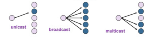
Explain unicasting, multicasting, and broadcasting
Unicasting is the process of sending data from one sender to one specific receiver,
Multicasting is sending data from one sender to multiple selected receivers.
Broadcasting is sending data from one sender to all potential receivers in the network.
**State the difference between bit rate and baud rate
| Parameters | Baud Rate | Bit Rate |
|---|---|---|
| Basics | The Baud rate refers to the total number of signal units transmitted in one second. | The Bit rate refers to the total Bits transmitted in one unit time. |
| Meaning | Baud rate indicates the total number of times the overall state of a given signal changes/ alters. | Bit rate indicates the total bits that travel per second. |
| Determination of Bandwidth | The Baud rate can easily determine the overall bandwidth that one might require to send a signal. | The bit rate cannot determine the overall signal bandwidth. |
| Generally Used | It mainly concerns the transmission of data over a given channel. | It mainly focuses on the efficiency of a computer. |
| Equation | Baud Rate = Given Baud Rate / Total Bits transmission in a signal unit | Bit Rate = Total Bits transmission in a unit of signal x Bit rate |